


I. Why design a plastic injection molding machine screw?
This is the first question that arises when talking about this issue because customers when buying a plastic injection molding machine from a plastic injection molding machine company do not need to pay attention to the design because that need has been met by the plastic injection molding machine company. So in what cases does the need to design a plastic injection molding machine screw appear?
1. Change the production plastic strain.
There are many different strains of plastic on the market, each with different properties, so there will also be a need for screws with different designs to suit each type.
If the design is not suitable, there may be an error of not being able to get the plastic; irregular plastic retrieval time; the plastic has not reached maturity when sprayed into the mold....
2. Screw barrel lifting/Screw barrel lowering.
Changing the screw diameter and length requires redesign.
3. The old design does not meet the needs of use.
The shaft does not have the color mixing function but starts producing color products.
Plastic adheres to the screw shaft causing black marks on the product
Slow resin extraction time, resin not visible
4. Old design does not guarantee durability
Wear and tear
II. Plastic injection molding machine screw design
II.1 Function of plastic injection molding machine screw
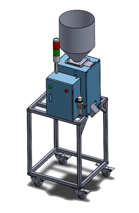
The plastic injection screw is an important component in the plastic injection machine. It is a spiral shape that helps transfer raw materials in granular form from the hole to the plastic nozzle in liquid form.
Refer to the following video to clearly understand its uses
II.2 Structure of plastic injection machine screw
The basic screw is composed of 3 parts:

🔹 Screw part
The screw part is a screw-shaped section consisting of 3 regions: feeding region, compression region, and dosing region
– Material region: The task is to push the plastic particles from the hole down the plastic to go around the cylinder barrel.
– Compression zone:: The task is to compress the plastic volume from a large volume to a smaller volume (because the plastic changes from a stacked particle structure to molten plastic)
– Quantitative area:: The task is to stabilize the structure of the liquid mass to prepare for injection into the mold.
Depending on the type of plastic, the ratio of the length of these segments to the diameter will be different, and the compression ratio of the compression zone will also be similar.
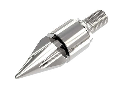
🔹 Threaded part and centering hole
– The threaded part is used to assemble the rocket head onto the screw
– Centering hole to center the rocket head and screw, limiting the phenomenon of rotation when the rocket head rotates.
🔹 Shank & key part
This part is to connect and drive the machine capacitor
To handle rotational motion, a key is needed (there are many different types of keys according to the manufacturer's design, the most common are flat key, rectangular key, stem key...)
.

III. Plastic injection molding machine screw design
Step 1: Clarify the problem: Clarify the reason for designing the screw shaft according to the reasons mentioned in Part I.
Step 2 Depending on each problem, different ways of handling will be determined.
2.1. Change the plastic type, the current shaft does not meet the pressing mode.
This case occurs when the two types of plastic before and after are too different in properties.
For example, switching from producing ABS plastic for household appliances to PET plastic for producing cable ties ➜ will not be able to produce cable ties that meet requirements.
➜ Redesigned screw section to accommodate new plastic
2.2. Switch to color plastic injection molding, current shaft is discolored
Because the current shaft does not have the function of mixing plastic, the color is not mixed evenly.
➜ New design, additional spiral groove and star fruit segment added to increase plastic mixing ability
2.3. Irregular plastic collection time
Similar to section 2.1; error occurs due to inappropriate design
2.4. Plastic adheres to the screw causing black marks on the product
Caused by design and surface finishing technology. The design has resin retention points that lead to carbonization and cause defects.
Because the plastic has high adhesion, the screw surface is not smooth enough, so the plastic sticks to it a lot, causing carbonization.
➜ Change the design so that there is no part that causes resin retention, choose the appropriate surface finishing method.
2.5. Raise / Lower shaft diameter
Does changing the diameter involve changing the type of plastic used? If the type of plastic is not changed, the design remains the same, only the diameter is changed accordingly. If the type of plastic with different properties is changed, the entire design needs to be changed.
Note that changing the shaft diameter must still meet the original assembly size (some cases will use an intermediate flange)
For a better understanding of the case of lifting and lowering the barrel, please refer to the article on lifting and lowering the screw barrel in the related article below.
Step 3: Design a new screw to meet the given requirements
3.1. Parameters related to the screw helix
.

– L/D ratio (Length of the helix divided by diameter), this ratio is from 14 to 26 depending on the type of plastic. The ratio of 20.5 is a relatively common ratio.
– Ratio between the helix parts. Length between the plastic intake part; compression part; quantitative part, this ratio also depends on the plastic codes
– Compression ratio = (Outer diameter – inner diameter of the feeding area) / ((Outer diameter – inner diameter of the measuring part). This ratio is between 2 and 4, commonly 2.5
– Plastic volume for 1 twist: This parameter is related to the load that the screw shaft must withstand and is also related to the shaft feeding speed.

3.2. Double twist and starfruit twist
Double twist is often designed in the quantitative area when the plastic is completely in liquid form, the mixing effect here will be maximized
The starfruit twist will be at the head of the shaft, usually 2 opposite spirals

3.3 Screw shaft shank
The shank will change little because it must ensure the ability to assemble and transmit. The most changes are when lowering the screw shaft diameter because at that time the assembly part should not be made like the original shaft because if so, the shank will be larger The diameter of the helix makes it impossible to remove the screw for maintenance in the usual way (remove the adapter and pull the shaft out) but must remove the entire cylinder and then remove the screw from behind the cylinder.

ASG Vietnam Engineering Company Limited is a unit specializing in handling plastic injection problems with more than 10 years of experience. We are always ready to listen to your questions 24/7 according to Hotline 0917.54.88.11
